With this software update the Arduino Spot Welder will now recognize if the foot switch is wired wrong and display an error message.

Detailed Description:
The foot switch needs to be used in no configuration, if it is connected in nc configuration an error message will be displayed during the start up of the spot welder.
- NO: (normally open) means contacts are open when the switch is not pushed
- NC: (normally closed) means contacts are closed when the switch is not pushed
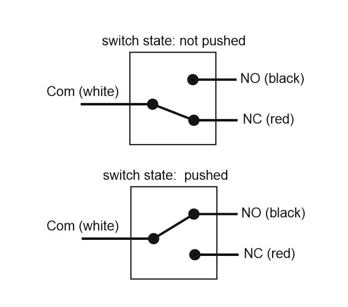
How to connect the foot switch correct
As you can see in the picture, the current batch of foot switches need to connect the white and black cable to the spot welder. This way you close the contacts when pushing the switch, which then activates a pulse.
If white and red is connected the welder will display the error message.
In case you manage to connect completely wrong and use red and black, there will be no error message but pressing the foot switch will also not work because these to contacts are never closed together no matter if the switch is pushed or not.
Software Download:
V3.3.1 of the Arduino Code is available to download at Github: Arduino Code Download
KICAD R1 resistor in version 3.3 should be modified to 1Kom ?
I see in other version is for 150 ohm resistor SMD 3521 2w
However, version 3.3 was changed to 1206 1kom
Is a bug?
I have a question… i build 3.2 spot welder version and i make a probe with 12 volt 77Ah auto batery (760cca)
Spot welder cable 7awg 40cm . But with 3 ms(PROBE) bourn the IRFB7430 . Please help me resolve this problem what is wrong??
Thanks in Advance
Robert
Its hard to tell whats the problem. Maybe something was shorted out, so the mosfets did not see the current just 3ms but way longer and then failed.
Hi i received my spot welder this week and i had a foot switch error, i had everything good connectic like the assembly instructions. when i made the foot switch open i saw that it was rong connectic not like the picture on your site. I had NO: (normally open) RED and NC: (normally closed) Black i changed them and everything was ok .
Thanks for the comment. The assembly instructions have been updated, so they match the current version of the foot switches.
It should now be more clear which cables to use.