PCB Set V3.3 Assembly Instructions
This instructions will show you how to populate the DIY Arduino Battery Spot Welder PCB Set V3.3 with all the componenets and how to assemble it.
What you need
- PCB Set V3.3
- Aluminum Parts
- components (see the BOM)
- tools (soldering iron, tweezers, screw driver etc.)
Populating the Arduino Board

- start by tinning one pad for each of the smd components
- this will make it easier to assmble the compnents to the board later

- on the V3.3 arduino board you can choose to populate R17 – R24 with 30 Ohm resistors or simply bridge the pads with solder
- when populating with 30 Ohm resistors the arduino board will be compatible to all V3 mosfet boards
- when bridging the pads the arduino board can only be used with V3.3 or later mosfet boards
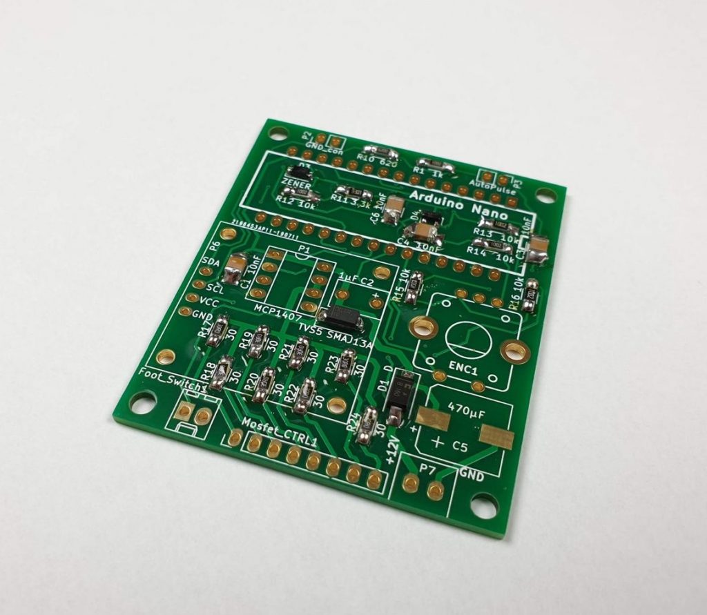
- populate all the small smd components first
- to do this hold the compnent you want to assemble with tweezers and solder one side to the already tinned pad on the pcb
- then you can solder the other side of the component
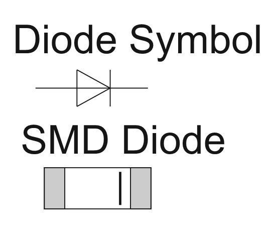
- make sure to assemble the diodes in the correct orientation to the pcb
- take a look at the pcture to see which way arround they need to be assembled
- the diode symbol is printed on the pcb to let you know the orientation of the component

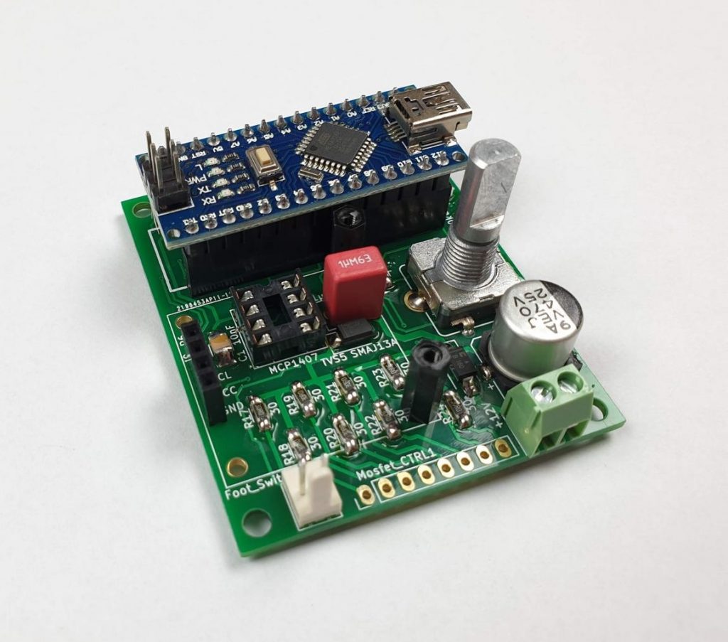
- now populate the big smd capacitor and the medium sized through hole components
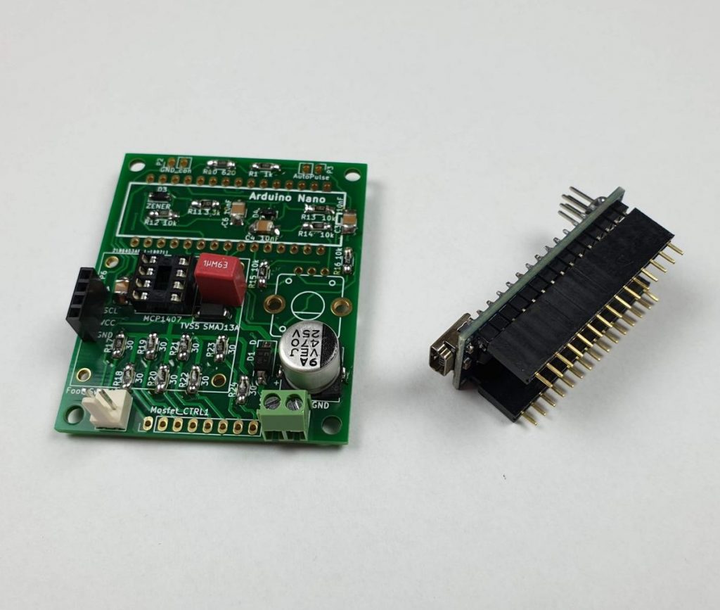
- when populating the two 15 pin female headers for the Arduino Nano there is a simple trick
- stick the headers on the Arduino Nano first
- then stick the Arduino Nano with the headers to the pcb and turn it upside down
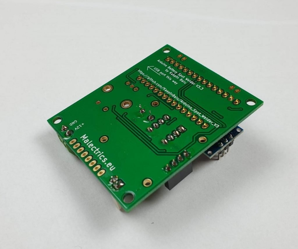
- make sure you got the Arduino Nano facing the USB port to the correct side of the pcb
- now you can easily solder all the pins of the headers
- next populate the rotary encoder and screw 2 M2x12 standoffs with M2 screws to the pcb
- the standoffs are not necessary for functionality but make the display assembly more rigid
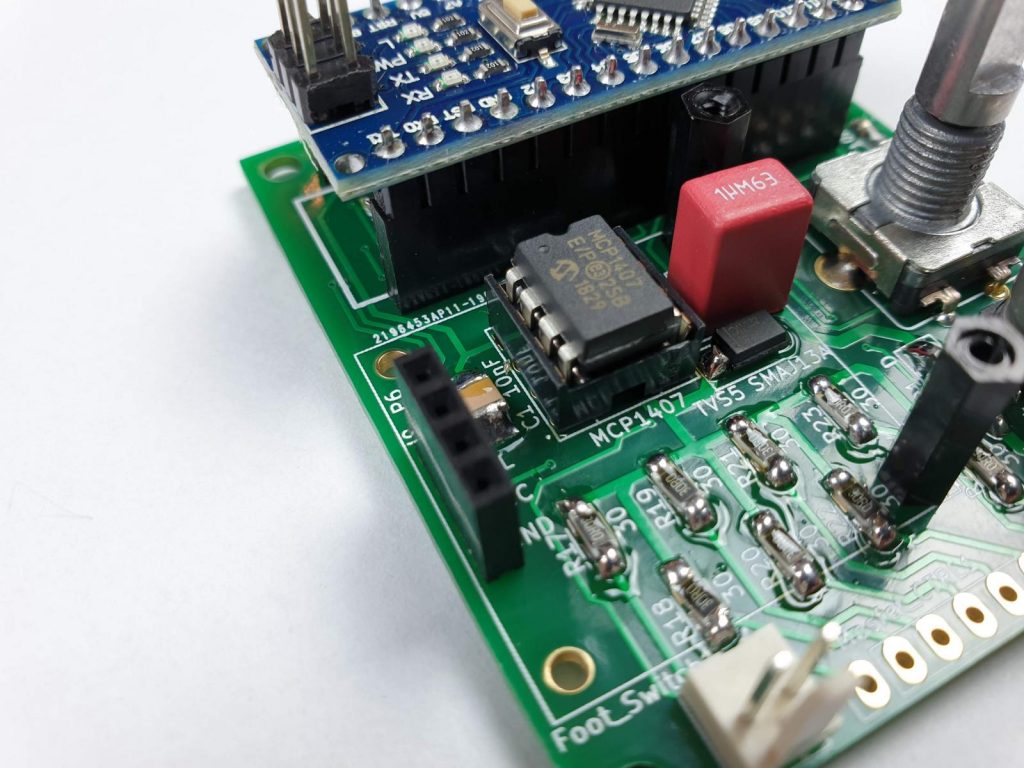
- plug the mcp1407 mosfet driver into its socket
- make sure the little notch on the mosfet driver is facing to the Arduino Nano
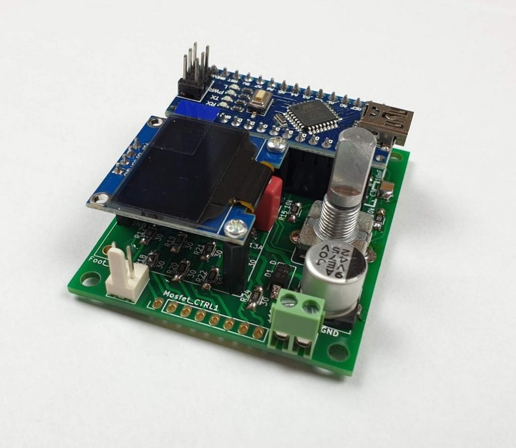
- plug the oled display into the 4 pin header and secure it with M2 screws to the standoffs
- make sure you got a display with the correct pinout on the 4 pin header
- it needs to be GND – VCC – SCL – SDA
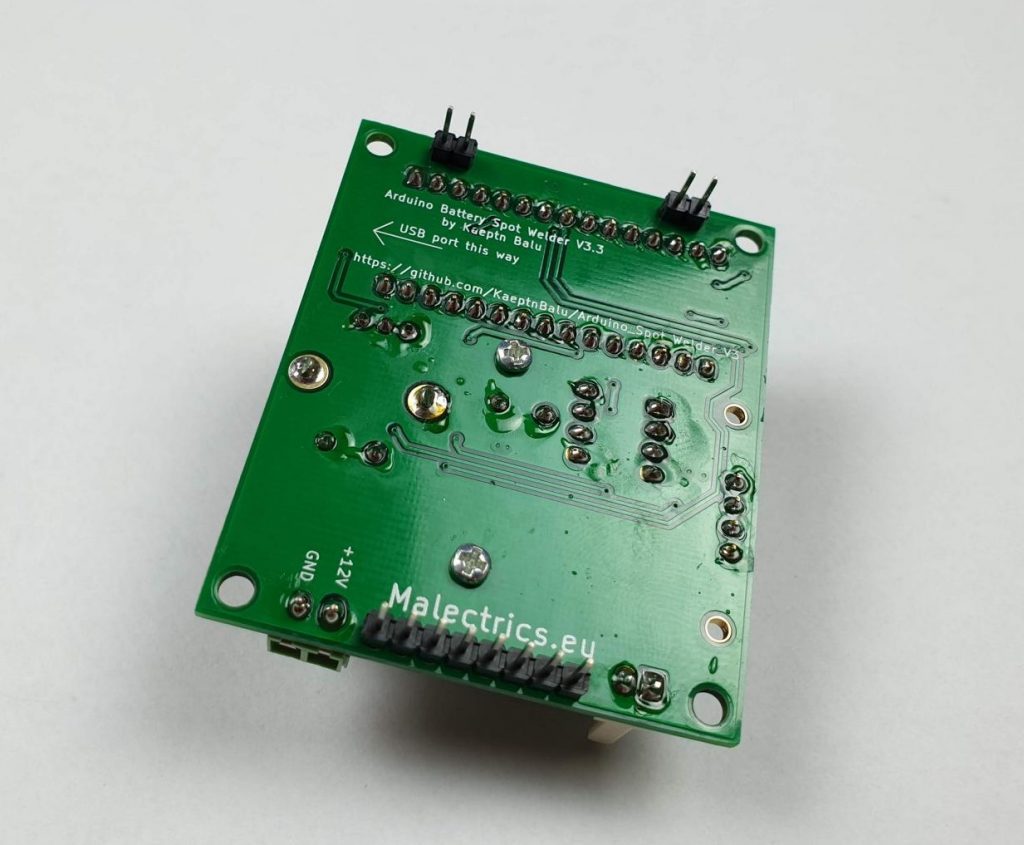
- finally break the long female header into two 2pin headers and one 8 pin header
- solder the female pin headers to the bottom side of the arduino pcb
Populating the Mosfet Board
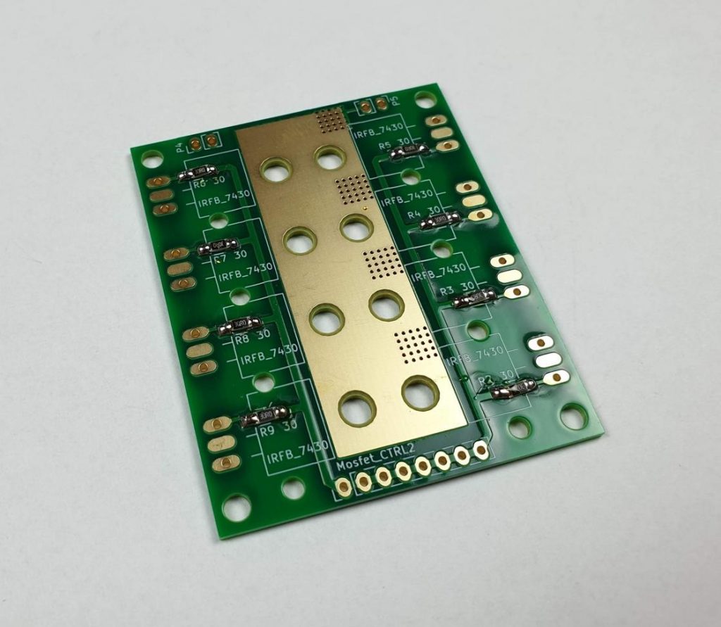
- start the mosfet board assembly by populating the eight 30 Ohm resistors
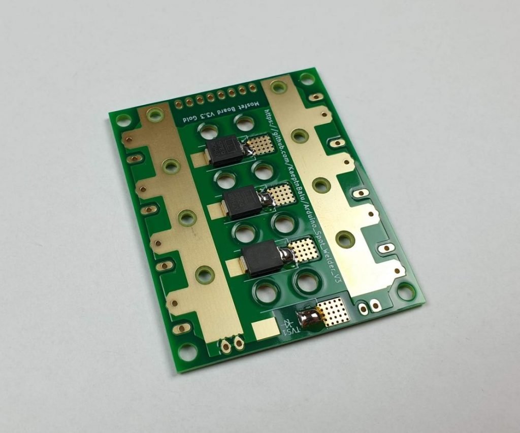
- then solder the 4 big TVS protection diodes to the bottom of the pcb
- do it the same way as with the smd components on the arduino board
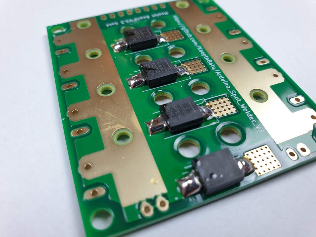
- make sure you got the orientation off all TVS diodes correct
- this is very important, otherwise you will get a massive short circuit through the diodes when touching the welding tips to the nickel strip when trying to use the welder
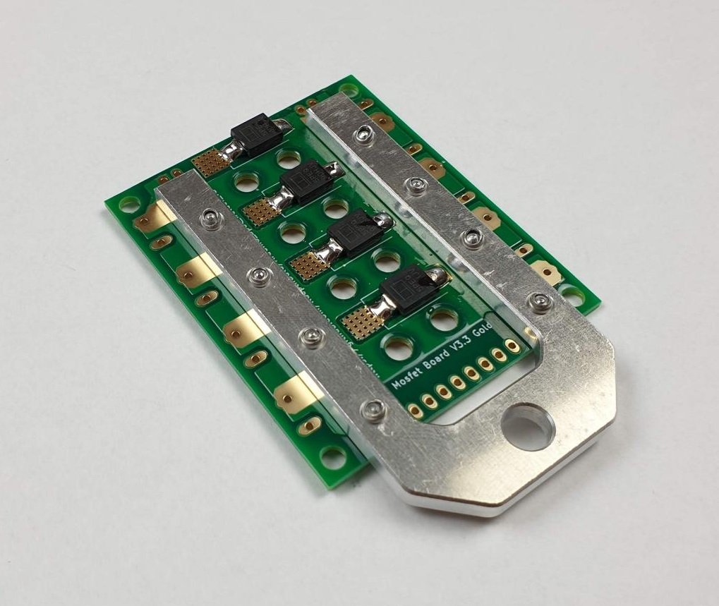
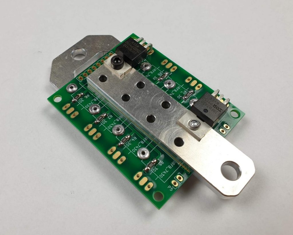
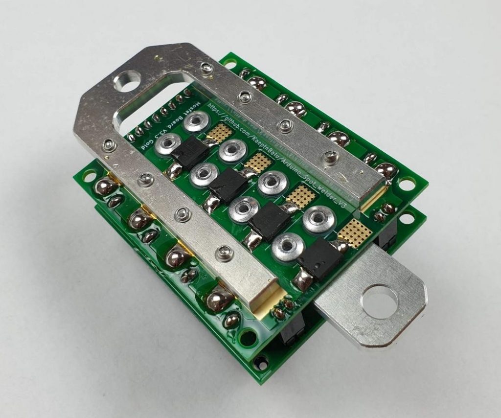
- now attach the u-shaped aluminum part to the pcb
- this can be done with 2.4x8mm rivets or using M2.5 screws and nuts
- the benefit of using rivets is that these connections can not come loose over time e.g. from vibrations
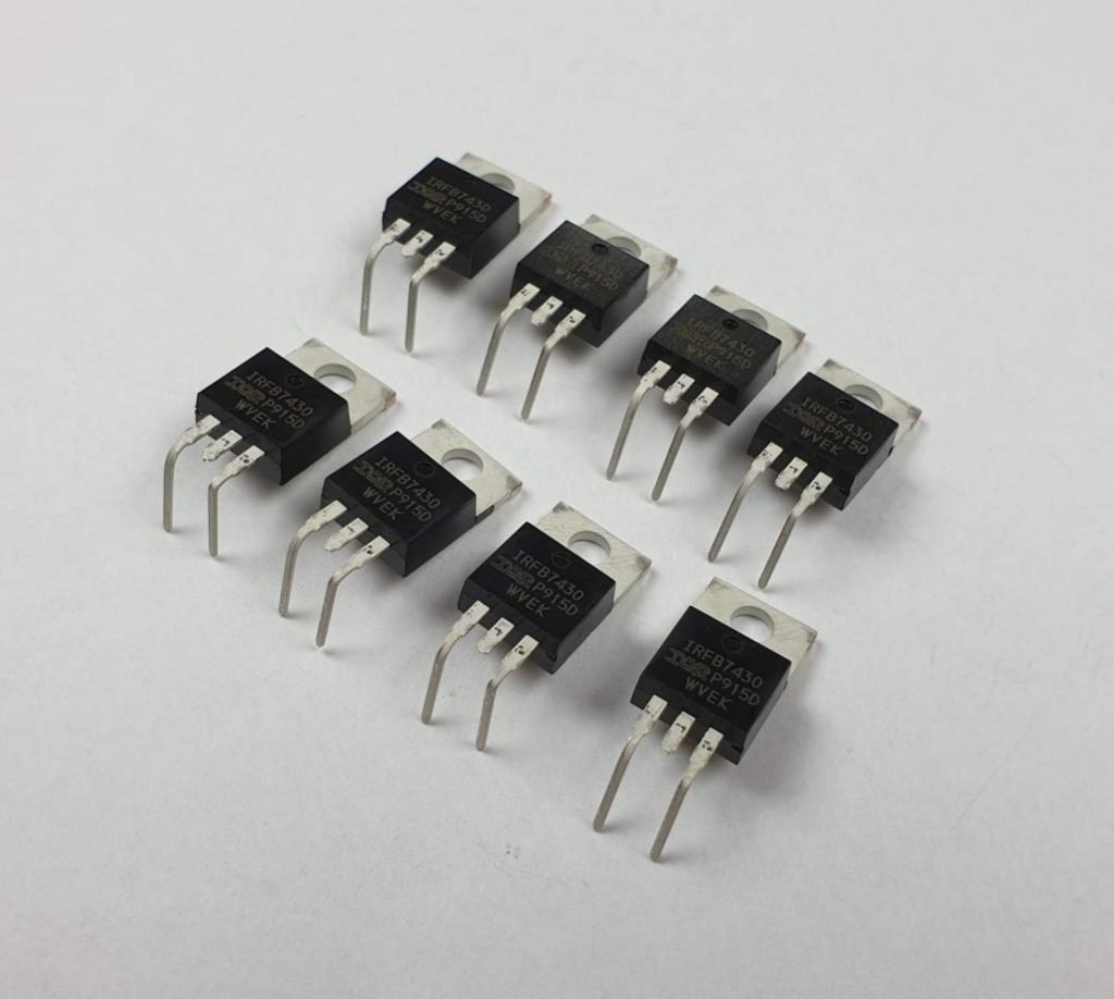
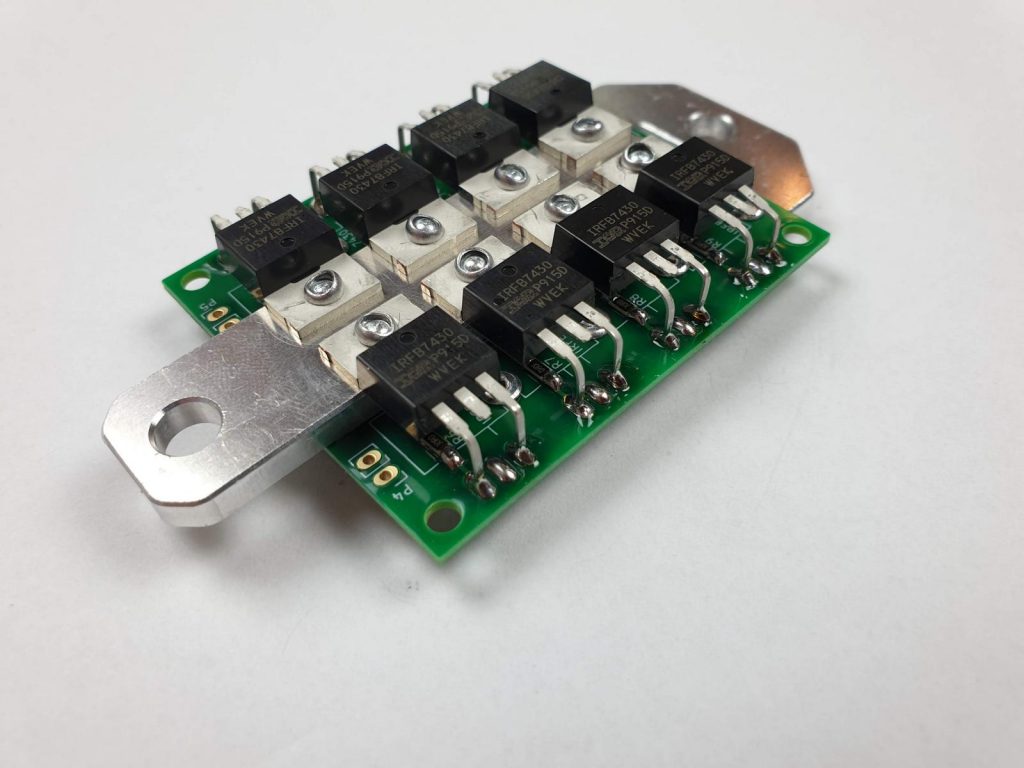
- next prepare the mosfets
- bend the legs about 90 degrees
- cut of the middle leg on each mosfet
- the mosfets can be assembled with M3x10 screws and nuts or 3.2x10mm rivets to the pcb and the straight aluminum part
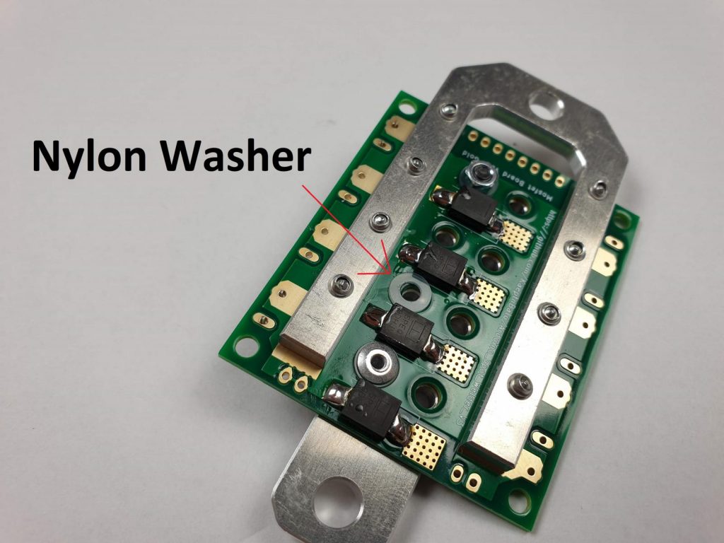
- do not forget to put nylon washers on all 8 screws/rivets on the bottom of the pcb to prevent them from scratching the pcb surface
- if there would be contact to the bottom copper layer on the pcb, that would cause a short circuit between the straight and the u-shaped aluminum part.
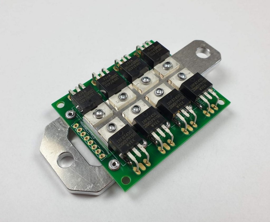
- when all mosfets are assembled it should look like this
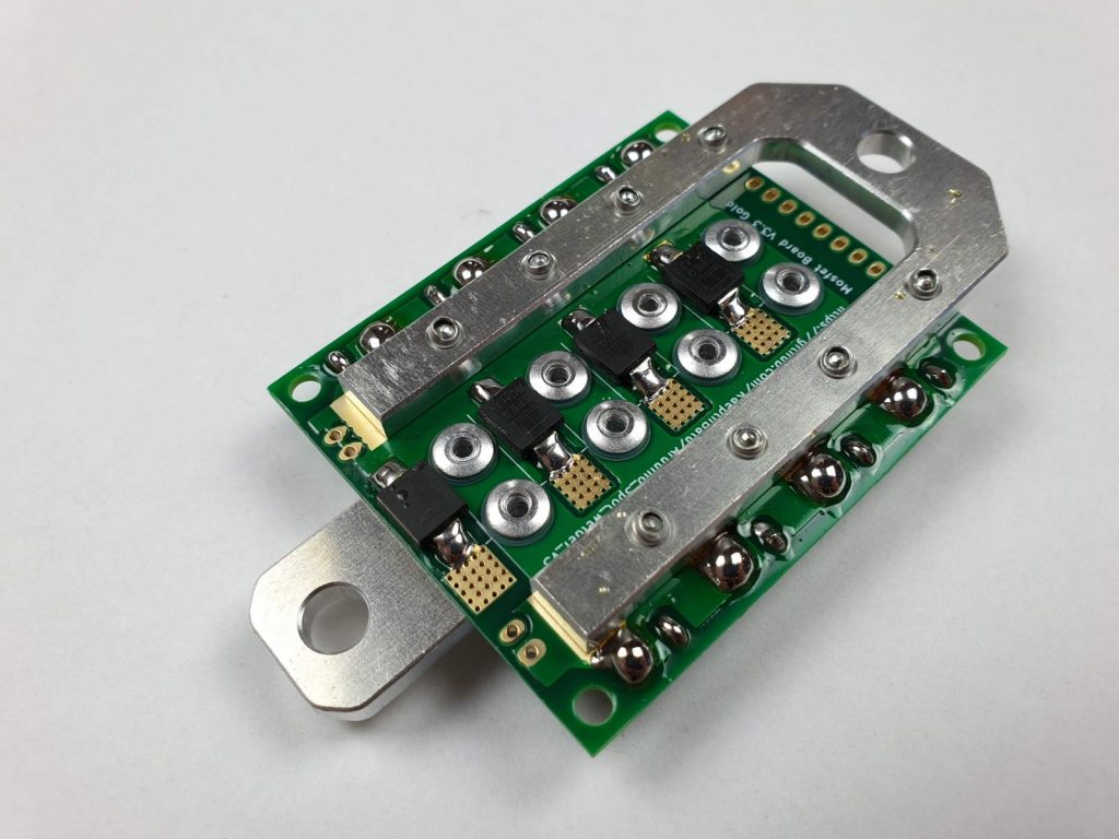
- solder the mosfets legs to the pcb
- add plenty of solder to the big pads on the bottom of the pcb because these are the connection where the high current has to go through
- on the top side of the pcb only the outer pads where the mosfets legs go through need to be soldered
- the middle pads are not connected to anything and can be tinned or left untinned depending what look you prefer
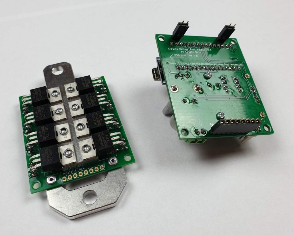
- to solder the female pin headers to the mosfet board you can use the same trick as on the arduino board
- stick the female pin headers to the male pin headers on the arduino board

- then stick the arduino board to the mosfet board
- now you can easily solder all the pins of the female pin headers to the mosfet board
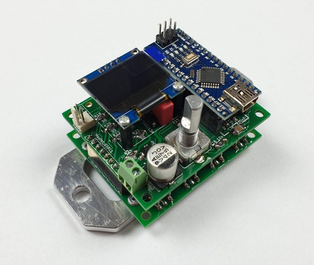
- thats it ! You just finished the assembly !
- next step is to upload the Spot Welder Software to the Arduino Nano
- for this check out the Software Upload Tutorial