The Arduino Spot Welder Mosfet Board just got updated to V3.3
The improvements in this new version are:
- Much wider traces on the bottom of the pcb for the high current connection to the u-shaped aluminum part
- Mosfet gate resistors directly on the mosfet board, very close to the mosfet gate pins
- All 8 Pins of the female 8 pin header that connects the Arduino and mosfet board are now connected to each other, which eliminates contact problems.
- compatible to all Spot Welder Arduino Boards V3 or later


Wider Traces
The hole for the middle pin of the mosfets legs has been removed from the mosfet board. The middle pin was not used anyway, because the current is transfered through the big top part of the mosfet that is screwed to the straight aluminum part.
This allowed to make the trace that has to transfer the high current from the outer pin of the mosfet to the u-shaped aluminum part much wider. The benefit of this is that the current can spread over a bigger area of the pcb that will make the pcb more robust to very high currents.
The pad for soldering the middle pin of the mosfets is still there but only at the top of the pcb. When building the mosfet board you can decide to simply cut off the middle mosfet pin or just shorten it a bit and solder it to the pad. This has no effect on functionality, its only an optical choice what look you like better. Prebuilt Kits will come with the midlle pin cut off.
Gate Resistors close to mosfet gates
Having the gate resitors very close to the mosfet gates prevents “swinging” in the gate voltage. That results in better mosfet switching synchronisation and less stress for the mosfets. It also made it possible to connect all 8 pins of the 8 pin female header together. This way it is no longer a problem if there is bad contact on one of the 8 pins of the header. All mosfets will always turn on or off exactley the same time.
What about the Arduinio Board ?
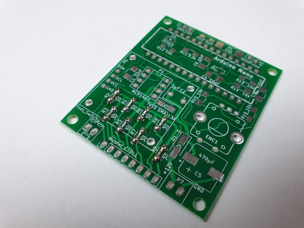
The Arduino Board does not need an update to be used with the new mosfet board. If you are going to populate the Arduino Board on your own you can use 30 Ohm resistors for R2 – R9 as before. Or if you dont have enough resistors simply bridge R2 – R9 with wire bridges like shown in the picture.
When populating R2 and R9 on the arduino board keep in mind that you need 8 additional 30 Ohm resistors for R2 – R9 on the mosfet board.
Congratulations for the streamlining of the MOSFET Board. Can it be made with 1oz layer or should be made with 2oz copper layer?
I would recommend to use at least 2oz copper. The current through this thin copper layer is very high.
Thanks for the advise!
KICAD R1 resistor in version 3.3 should be modified to 1Kom ?
I see in other version is for 150 ohm resistor SMD 3521 2w
However, version 3.3 was changed to 1206 1kom
Is a bug?
Hi,
You can use a normal resistor with 1k no problem.
The 150 ohm resistor is still in the design because in the earlier version of the welder an addidtional external protection diode was used.
This required the resistor to have such a low value.
Thanks for taking the time to reply
Perfect project!
I have recieved my v3.3.4 kit and are searching for a car battery. The manual says 400 to 600 cca but;
– is 300 also good enough?
-and what happens to the board when it reaches max current?
– what is the max current?
Tom 🙂
Hi,
300A might not be enough current to get good welds.
The best results are made with about 600A (CCA) car batterie size.
The maximum i tested the welder with was a 800CCA battery. Higher current may damage the mosfets or the protection diodes on the mosfet board.
Hey Marc,
Let’s say I need just a bit more juice. I have a 900 CCA battery that I would like to use.
If I damage a mosfet or the protection diodes, are they an easy replacement? Also, will my board start on fire or just shut down?
Hi,
Replacing the mosfets or diodes requires a powerful soldering iron, because the aluminum parts transfer the heat away very quickly.
But other than that it is pretty easy to do.
In case the mosfets fail only the legs should brake. They act kind of like a fuse then.
If a diode fails it will eject smoke and a little very short explosion. But it will not set the board on fire.
Thanks Marc! I might get a new mosfet board just in case on order and then report back.
Hey Marc,
Three more things
1) Can I just order a mosfet board? I did not see it on your website.
2) Did you not test higher amps due to lack of a 900cca battery or is it that the electrical theory for the diodes that says they will not take it and it does not make sense to try?
3) Can I upsize the fan/heatsinks to allow for more current?
I am repairing Tesla Model S packs with new fuses and the connection to the bus bar is not going well @ 725 CCAs and 100ms.
Mike
All for now.
1.) Its possible to get as replacement part. Please contact via email info@malectrics.eu
2.) and 3.) The diodes and mosfets are already stressed out pretty much at 800A car battery.
It may work with 900cca but will need good cooling and i dont know if lifetime of the mosftes / diodes is compromised then.
Hallo, brauche mal Eure Hilfe.
Auf meinem Board ist eine Diode defekt. Bezeichnung 5PEQ9DHJV. Finde mit dieser Bezeichnung keinen Händler.
Wer kann helfen bzw. welche Dioden anderer Bezeichnung würden funktionieren
Danke für eure Hilfe
Jens
Es ist denke ich diese Diode gemeint: https://www.mouser.de/ProductDetail/576-5.0SMDJ13A
Falls du noch andere Bauteile brauchst schau auch mal bei meinem github. Dort gibt es eine komplette Teileliste (BOM) von dem Welder. https://github.com/KaeptnBalu/Arduino_Spot_Welder_V3/tree/master/Parts
Hallo Mark. 1) Board v3.3, sollte ich R2-R9 auf beiden Boards installieren oder nur auf dem MOSFET-Board? 2) Warum kann die V4.03-Software nicht für die V3.3-Karte verwendet werden? Der einzige Unterschied ist der Zusatz von BUZ. 3) R2-R9, ist 0805 genug? Danke schön. PS, beim Schweißen sind 3 MOSFETs durchgebrannt, aber die Schutzdioden und R 30 Ohm funktionieren. Warum ist das so?
Hallo,
1. Die 8 Wiederstände sollten auf beiden Boards installiert werden. Auf dem Arduino Board könnten die Widerstände theoretisch auch einfach mit Drähtchen gebrückt werden. Sie sind nur dazu da um die Kompatibilität mit älteren Spot Welder Versionen aufrecht zu erhalten, da die frühen Versionen noch keine Widerstände auf dem Mosfet Board hatten.
2. In V4 ist zusätzlich moch ein Temperatur Sensor dazu gekommen. Wenn die Routinen für den Buzzer und den Temperatur Sensor entfernt werden, sollte es auch auf den V3 Weldern funktionieren.
3. Ob bei R2-R9 die kleineren 0805 dauerhaft fuktionieren habe ich noch nicht probiert. Müsst eman testen ob die mit der Verlustleistung zurecht kommen.
4. Die Schutzdioden schützen die Mosfets nur vor Spannungspitzen am Pulsende. Bei zu hohem Strom oder zu hoher Belastung (z.B. sehr lange Pulszeit mit hohem Strom oder sehr kurze Zeitabstände zwischen den Schweißpunkten) können die Mosfets unabhängig davon überhitzen / kaputt gehen.
Hallo Marc. Ich verstehe. Ich werde die fehlerhaften MOSFETs austauschen und versuchen, auf V4.03 zu aktualisieren. Meine andere Frage: Ich habe V3.3 (Wider Traces), aber auf der MOSFET-Platine steht „MOSFET Board V3.2“. Ist das die erste Version von Board? MfG, Alex.
Von dem Mosfet Board gab es noch ältere Versionen. V3 und V3.1 https://malectrics.eu/wp-content/uploads/2017/12/compare_V3_V3.1.jpg
Den Unterschied vom Mosfet Board V3.2 zu V3.3 findest du hier: https://malectrics.eu/2019/03/29/mosfet-board-v3-3-update/
Hallo Marc. Frage: 1) Nach dem Schweißen sehe ich die Daten – 2,5 V – 2,7 V, 270 A – 305 A. Nickelband (0.15) ist nicht verschweißt. Verzögerung 12, Impuls 20–90 ms. Ich verwende eine 60 A\H, 550CCA SAE-Batterie. Was könnte defekt sein, das SpotWelder oder die Batterie? 2) Ist es unmöglich, die Voltmeter-Messwerte im V403-Programm separat zu kalibrieren? Danke schön.
Da das Nickel Band nicht verschweißt wird scheint die Messung vom Spot Welder korrekt zu sein. Der Strom ist nicht hoch genug um gute Schweißpunkte zu bekommen.
Das kann an einem schlechten Kontakt liegen der den Strom begrenzt. z.B. die Verbindung von Schweißkabel zum Welder, die Batterieklemmen an der Autobatterie oder eventuell haben auch die Aluteile keinen guten Kontakt zu der Spotwelder Platine.
Es kann auch sein das die Autobatterie einfach nicht mehr genug Strom leifern kann. Ist die eventuell schon älter und war sie komplett voll geladen ?
In Software Version V4.03 wurde die kalibrierung der gemessenen Spannung entfernt, das es mehr Probleme verursacht hat als zu helfen. Wenn die Abweichung sehr groß war, war in der Regel der Arduino Nano defekt, so das es sich dann auch durch kalibrieren nicht beheben ließ. Im Normalfall liegt die Abweichung zur realen Spannung nur bei +- 0,1V – 0,2V was keinen großen Einfluss hat auf den berechneten Strom hat.
Hallo Marc. Ich verwende 1) Stromleiter aus 6 mm dickem Kupfer, 2) Kabel 50 mm2, 3) Stromspitzen aus einer Speziallegierung für Kontakte von Schweißgeräten. Wahrscheinlich beträgt mein Widerstand des gesamten Stromkreises weniger als 9 mOhm. PS. Da ich den MCP1407 nicht kaufen konnte, habe ich den MCP1406 verwendet. Das funktioniert auch super.
Die aktuellen Spitzen haben einen Querschnitt von 8×8 mm und sind wie eine Kugel geschärft….
Hallo Marс. Den Widerstand der Stromkreise überprüft. Der Widerstand des Kabels, der Stromspitzen und der Kupferteile beträgt 0,2 mOhm. Der Innenwiderstand der Batterie beträgt 15,6 mOhm. Ich füge Transistoren hinzu – ungefähr 0,2 mOhm. Insgesamt 15,8 – 16 mOhm.