Arduino Spot Welder V4 Car Battery Bundle Assembly Instructions
Assembly of the Prebuilt Kit
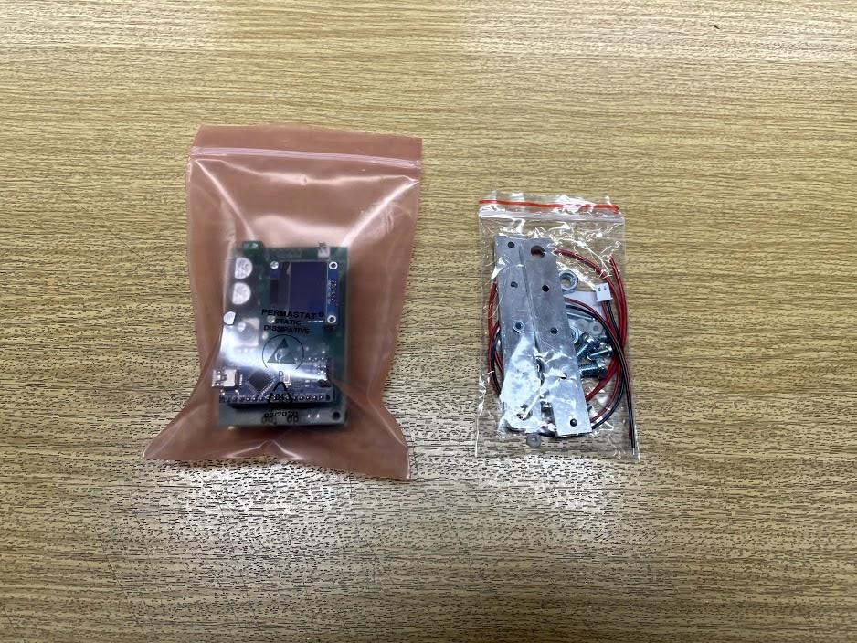
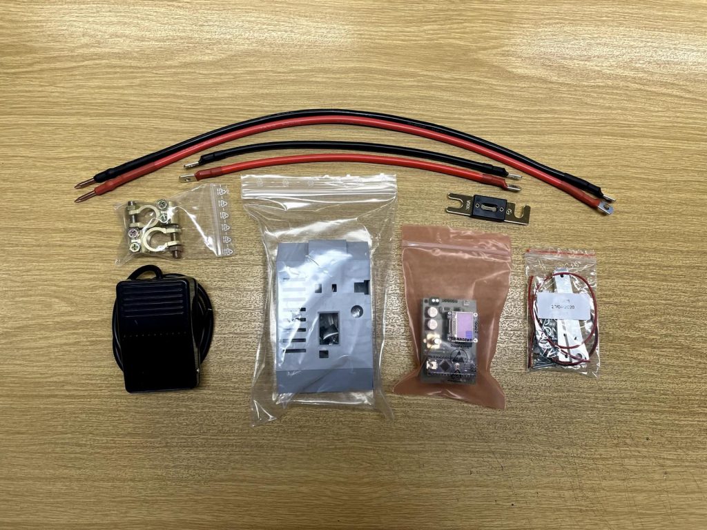
For this you will need the prebuilt kit and the little acessory bag that comes with it.
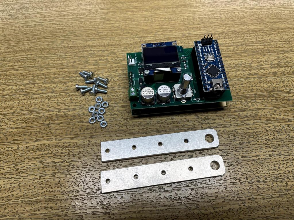
First you need to mount the aluminum parts to the mosfet board. For this you need the 2 aluminum parts, 8pcs M3x8 screws and 8pcs M3 nuts.
The aluminum parts can be a bit oily from the manufacturing process. Before mounting them please wash them with alcohol or soap to remove the oil. Clean parts will ensure a good electrical connection to the pcb.


Seperate the two halfes of the welder, then mount the aluminum parts with the screws and nuts to the mosfet board.
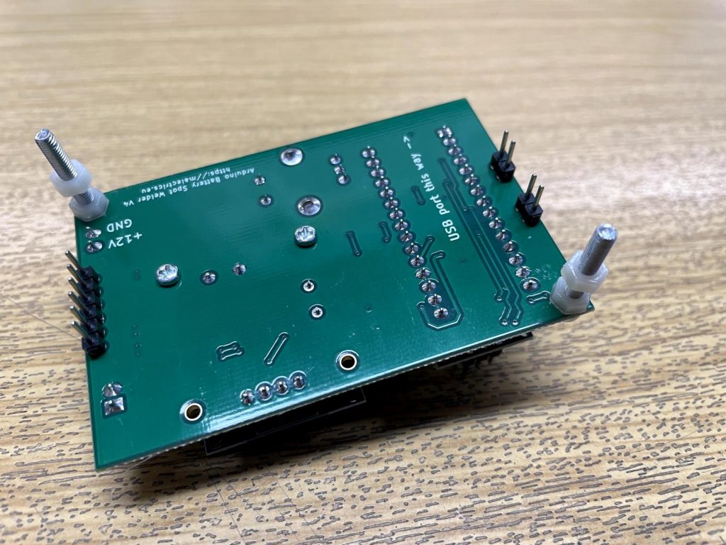
Take the top half of the prebuilt kit and insert two M3x20 screws into the top pcb. Secure the screws with an M3 nylon nut on each screw. Dont tighten the nuts to hard or they may break.
Then add one more M3 nylon nut on each screw. The distance between the two pcbs when they are plugged together is about 11mm. Screw the nuts to about this distance.

Put both halfes of the welder back together and secure it with one nylon nut on each screw.
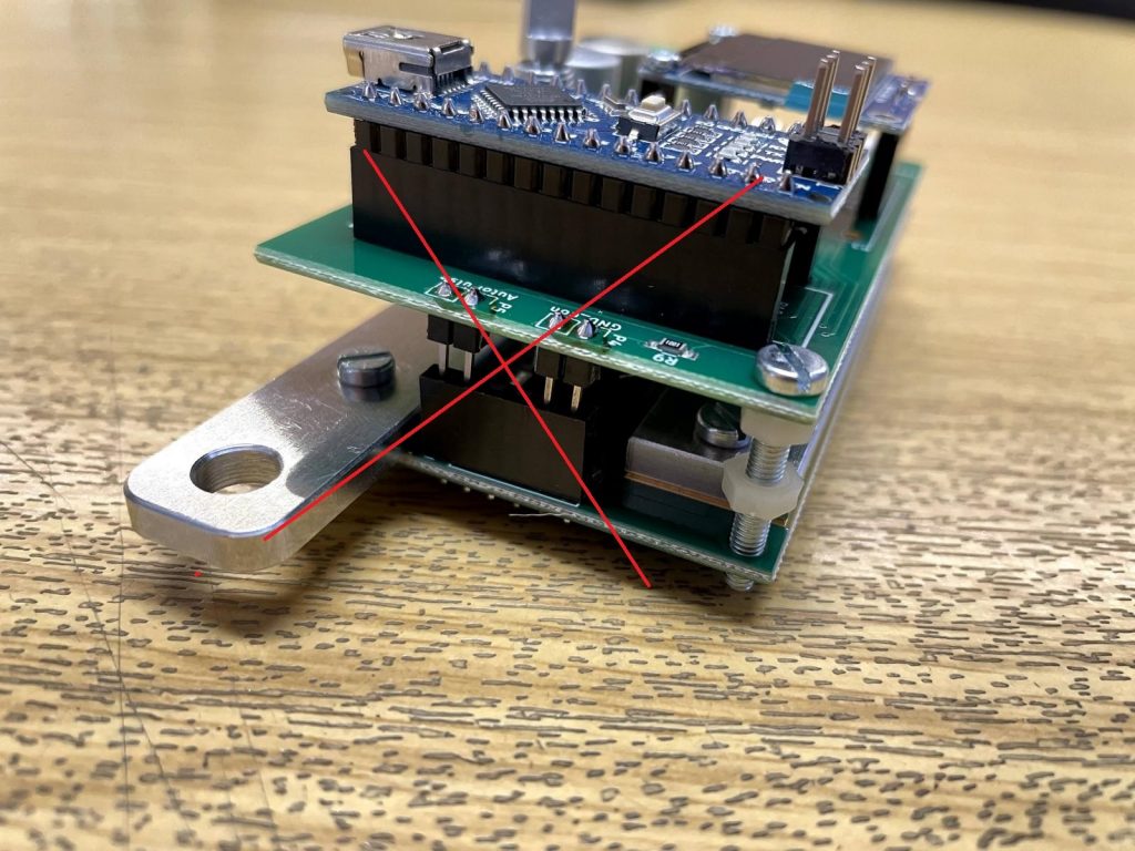
Make sure you put the halfes together correctly. The 6 pin header needs to go into the 6 pin socket and the 2 pin headers need to go into the 2 pin sockets. The boards will also fit together the wrong way arround but then the welder will not work.
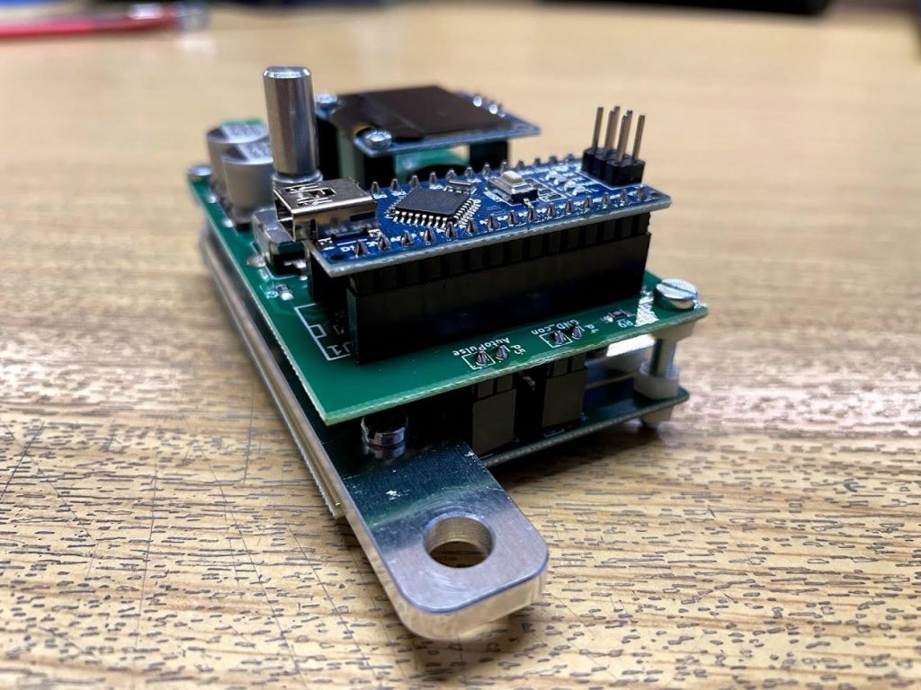
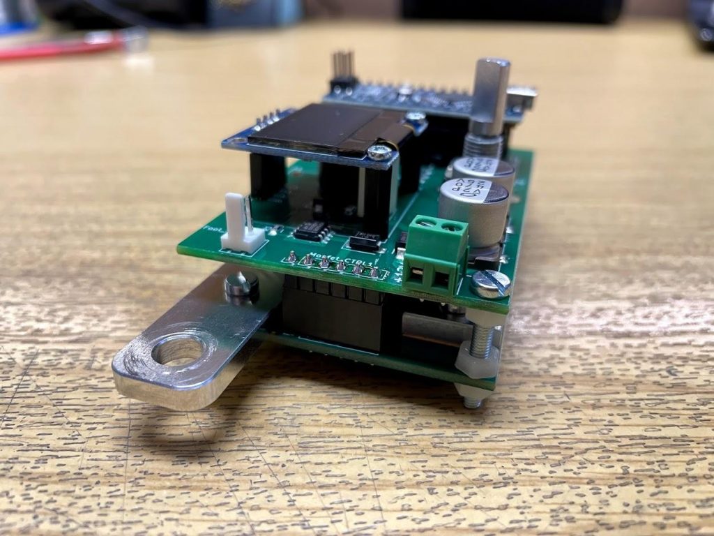
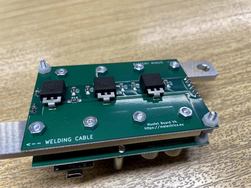
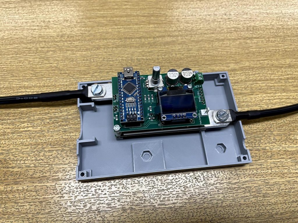
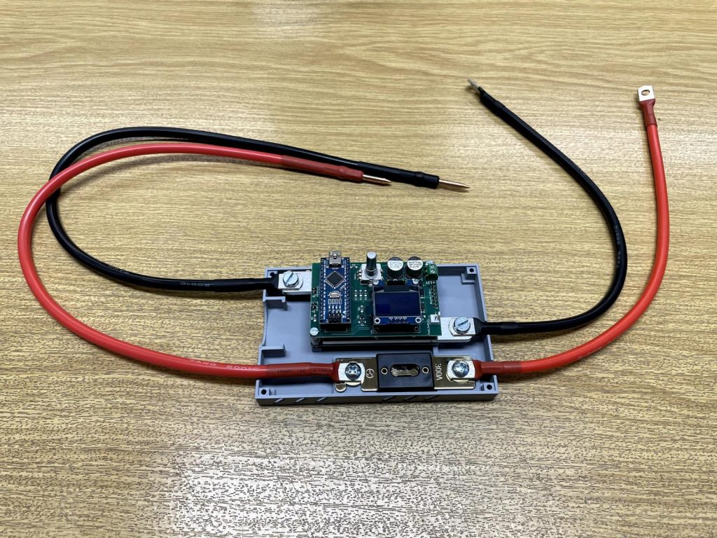
Correctly mounted it should look like this.
Mounting the cables to the prebuilt kit
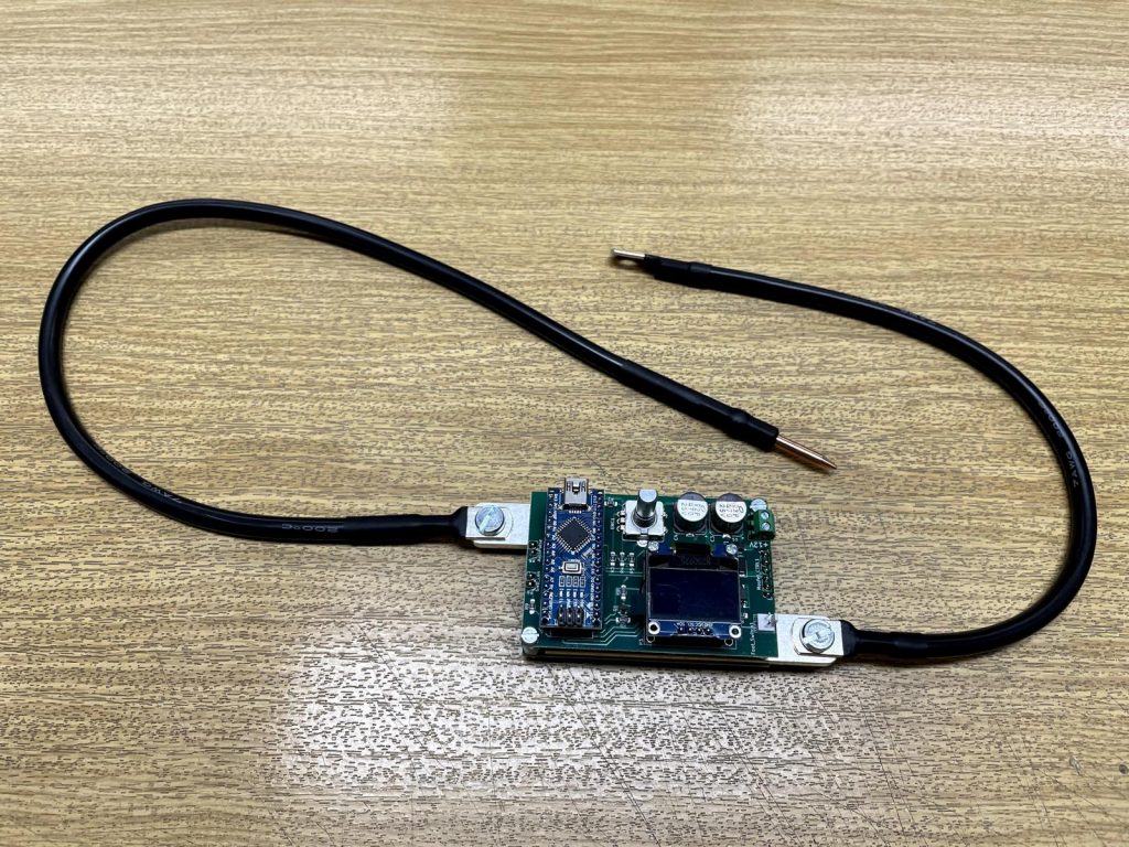
Mount the battery extension cable and the welding cable to the welder. For this use the M6x10 screws and M6 nuts from the prebuilt kit acessory bag.
Pay attention to the orientation the cable shoe is mounted to the aluminum part. The cable needs to be “in line” with the aluminum part. Otherwise later it will not fit in the gaps in the 3d printed case.
Make sure to mount each cable to the correct side of the welder. It is also written on the bottom of the welder which side goes to the battery and which is for the welding cable.

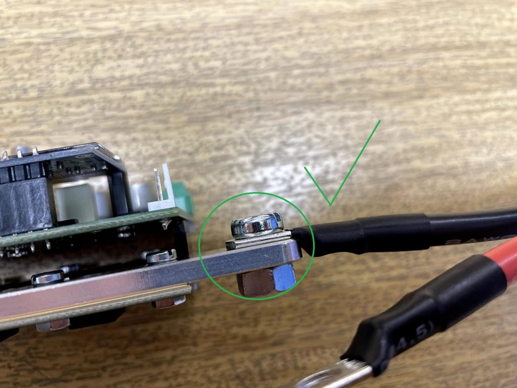
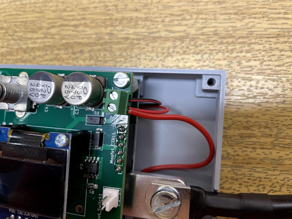
It is possible that on some cables the shrink tube on the cable shoe reaches a bit to much on the mounting surface. (See the picture)
Then you will have a little gap between the alu part and cable shoe when mounting it. In that case remove a bit of the shrink tube so it can be mounted flat onto the aluminum part for optimum electrical connection.
Prepairing the foot switch
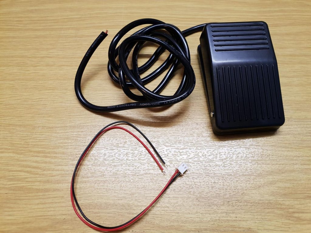
For this you need the foot switch and the cable with the white 2-pin connector from the prebuilt kits acessory bag.
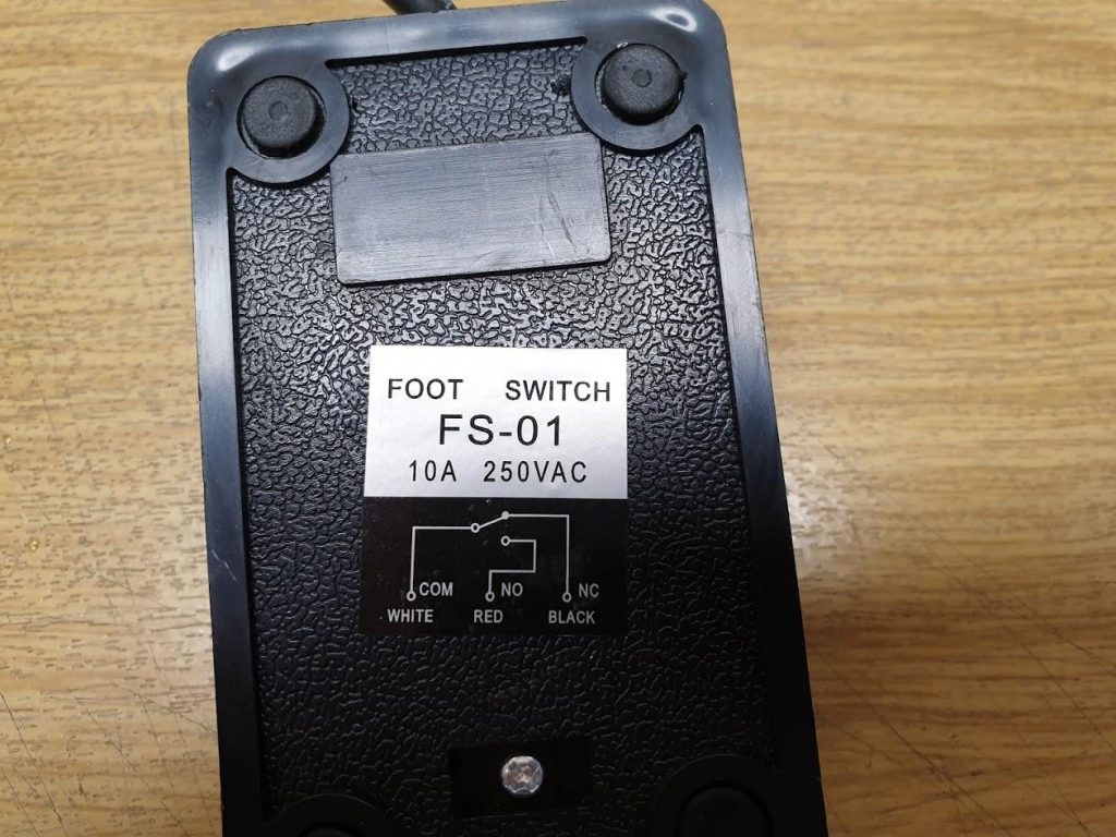
The foot switch needs to be operated in normally open (NO) configuration. This means it closes the contacts when it is pushed. Since the manufacturer of the foot switches tend to change cable colours pretty regulary you need to check first which colours are the correct ones to use.
To achieve this take a look on the back of the foot switch.There should be a sticker that shows the connections. For the foot switch on the picture you need to use the white and red cable.
But in another batch there might be foot switches that need the black and white cable to be operated in NO configuration.
Dont worry, you can not damage the welder by using the wrong cables. It will show you an error message if you use the wrong ones.
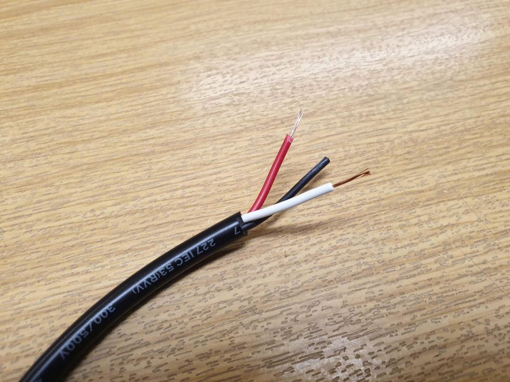
First remove about 4cm of the black isolation of the foot switch cable. Then remove about 1cm isolation from the cables ends.
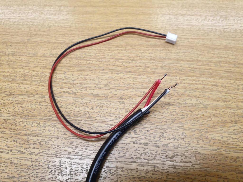
You can now simply solder the two cable ends to the cable with the white connector.
If you dont have a soldering iron remove about 1cm isolation from the cables with the white connector and twist them to the foot switch cables.
There is no polarity, so it doesnt matter if red goes to red and black to white or the other way arround.
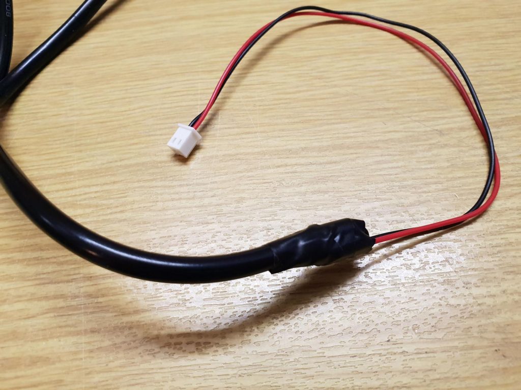
Isolate the connections with some electrical tape or shrink tube.
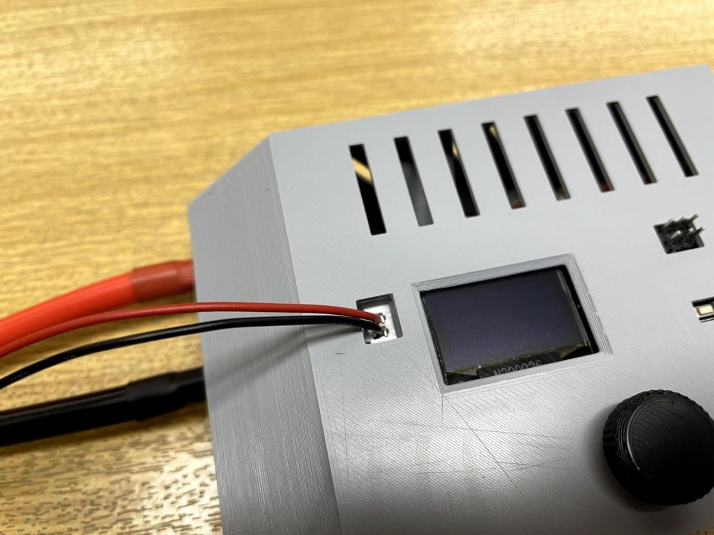
The socket for the foot switch is the white one on the spot welder pcb (you can see the location in the picture) It is also labeled “foot switch” on the pcb.
But dont connect the foot switch to the welder yet. It can be simply connected and disconnected after the assembly is finished.
Mounting the prebuilt kit in the case
Seat the prebuilt kit in the case
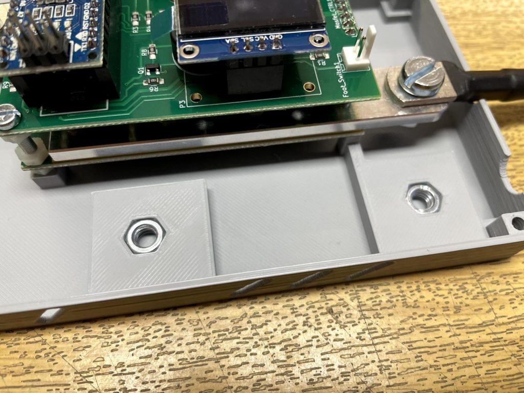
Now take the two M5 nuts from the 3d printed case acessory bag and insert them into the case.
The best method is to screw the nut a few threads onto the M5x10 screw and then insert it into the pocket.
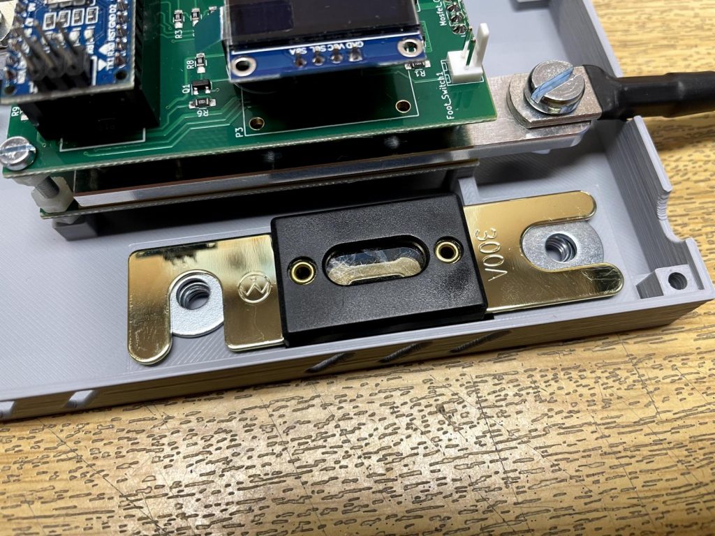
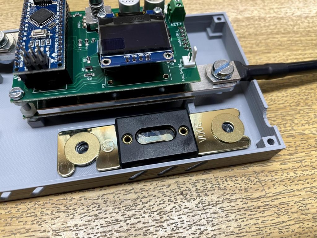
To mount the ANL 300A Fuse you need:
- 2pcs steel washers
- 2pcs brass washers
- 2pcs M5x10screws
- positive battery extension cable
- positive welding cable
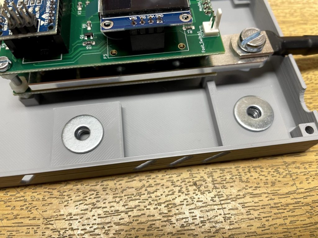
Place it in the following order on the nuts: steel washer -> ANL300A Fuse -> brass washer -> cable shoe of the cable -> M5x10 screw
Don’t fully tighten the screw for the welding cable yet.
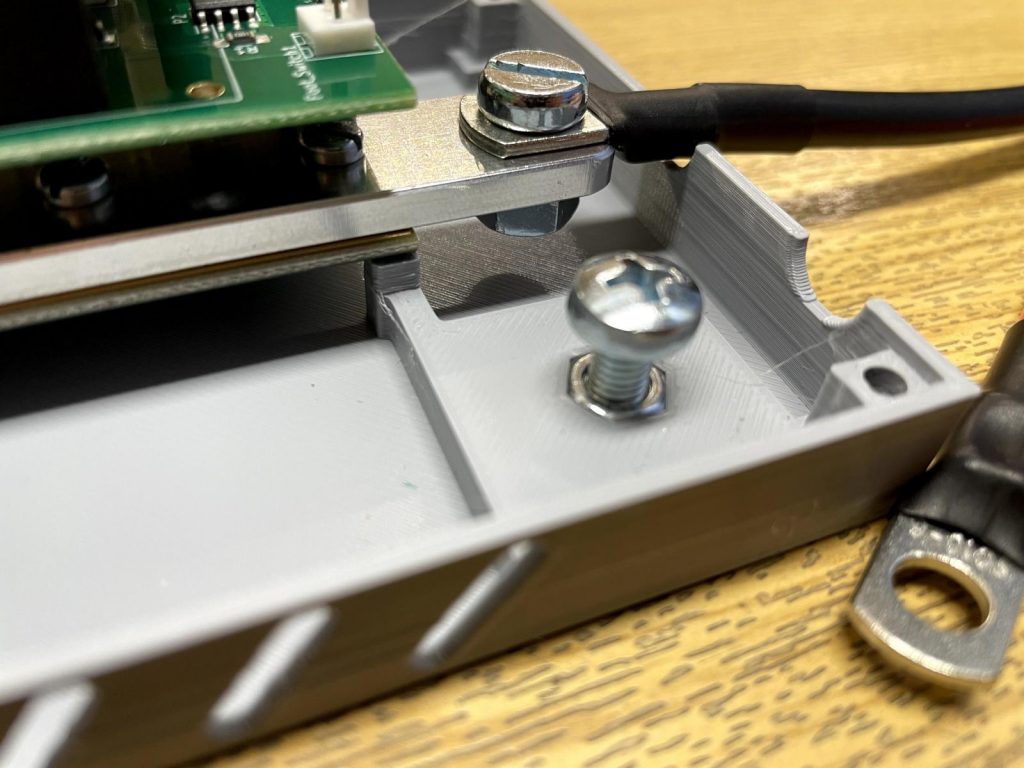
The assembly should now look like this.
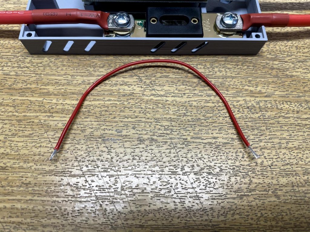
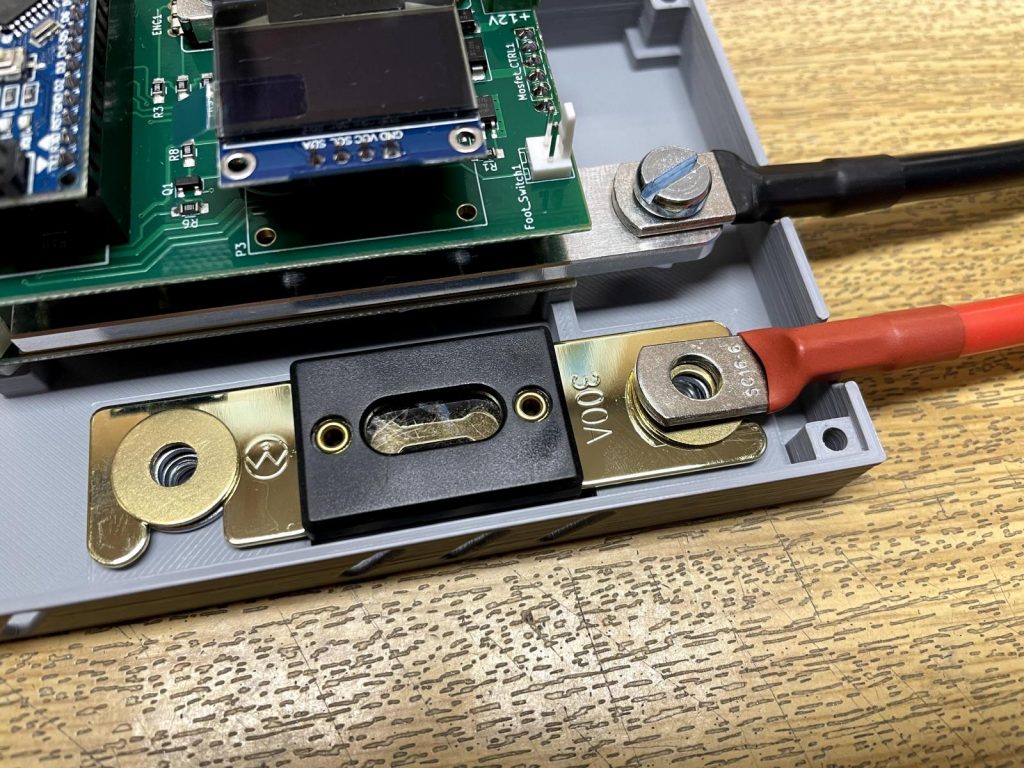
Take the red cable from the prebuilt kit acessory bag and shorten it to about 15cm. Remove about 5mm insulation from the cable ends.
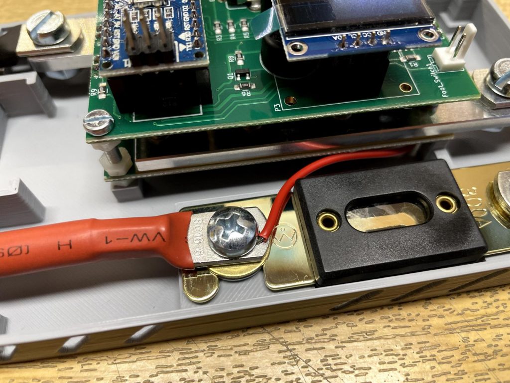
Clamp one end of the cable under the screw head on the welding cable side of the fuse. Now fully tighten the screw.
Dont clamp the cable between the cable shoe and the brass washer or between the fuse and the brass washer. These parts need to lay flat on each other to carry the high welding current.
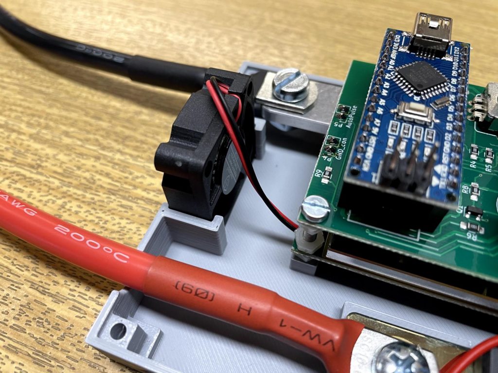
Insert the fan into the case and guide the cables underneath the prebuilt kit. The sticker on the fan should face to the inside of the case. This way it will blow air into the case and guarantee optimum cooling.
To insert he cables into the screw terminal first open it by turning the screws a few revolutions counter clockwise.
Then insert the negative fan cable to the side closer to the edge of the pcb and tighten the screw carefully.
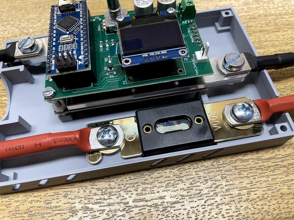
Next insert the positive fan cable together with the positive cable from the fuse into the other side. Carefully tighten the screw of the screw terminal and check if the cables are clamped properly.
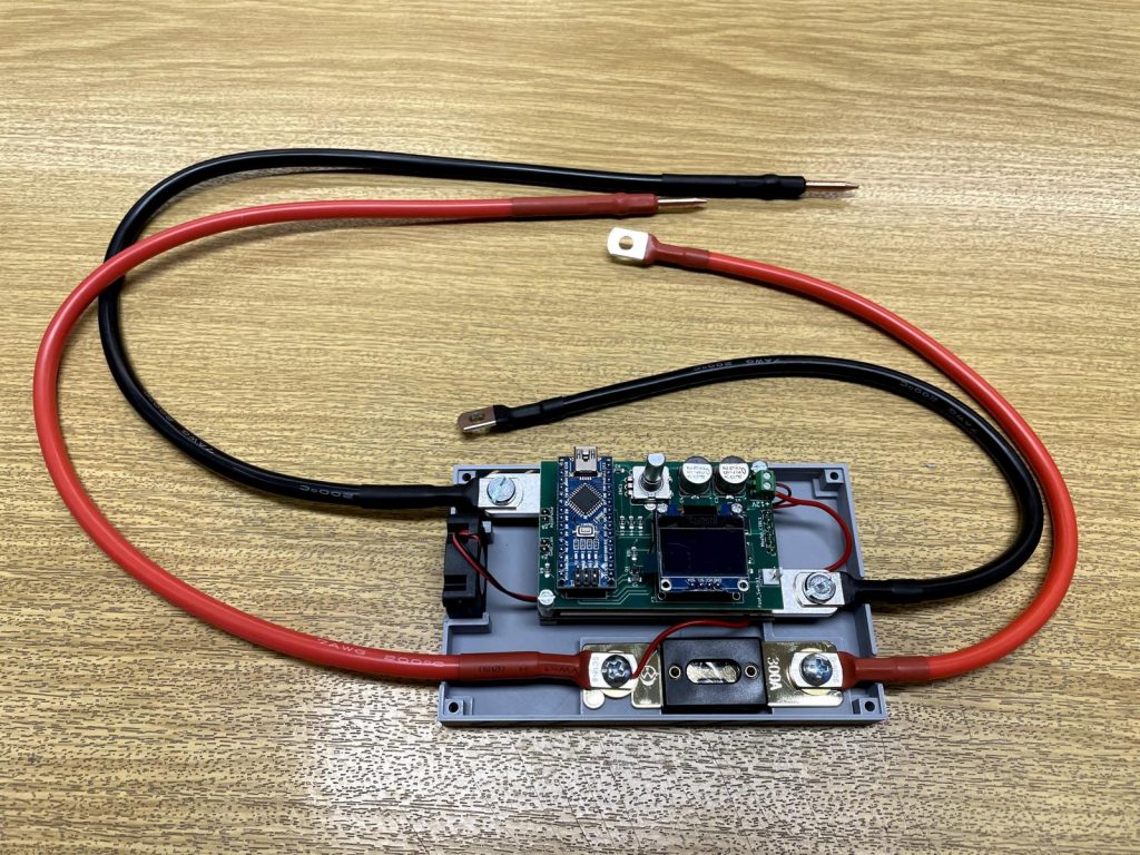
It should now look like this.
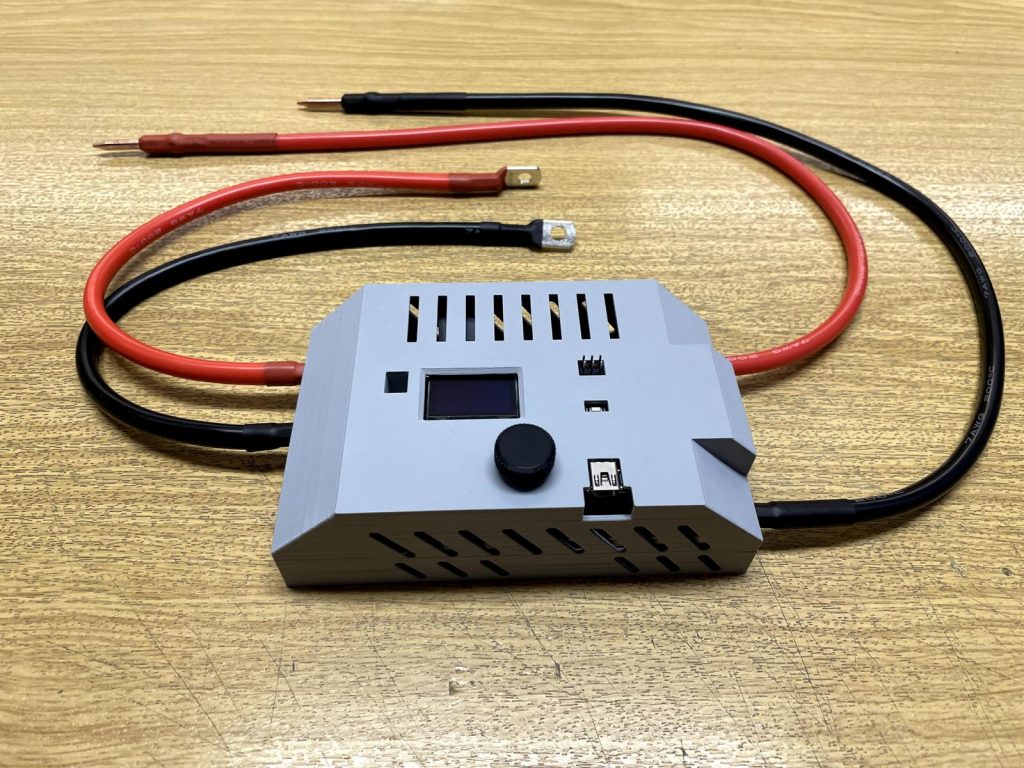
Take the top half of the case and stick it on. Also take the black rotary encoder knob and stick it on the rotary encoder shaft.
When sliding it on the rotary encoder make sure you align it corectly to the rotary encoders shaft. Dont push to hard so you do not damage the rotary encoder or the spot welder pcb.
Tip knob to tight:
Should the knob fit to tight on the rotary encoder heat the 3d printed knob with your hair dryer a bit. Then try to push the warm knob onto the rotary encoder. It should slip on much easier now.
Tip knob to loose:
If the knob sits lo loose on the rotary encoder and tends to fall of easily add a layer of painters tape arround the rotary encoder axis to make the knob fit more tight on it.
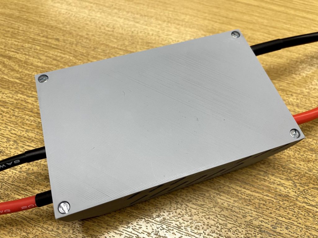
Finally you can fix the case halfs together with 4pcs M3x16 screws from the 3d printed case acessory bag.
The screws are self tapping in the top half of the case. To get them screwed in you need to push and screw them at the same time.
When both case halfs are pulled together dont overtighten the screws or you might break the self tapped plastic thread.
Mounting the welder to the car battery
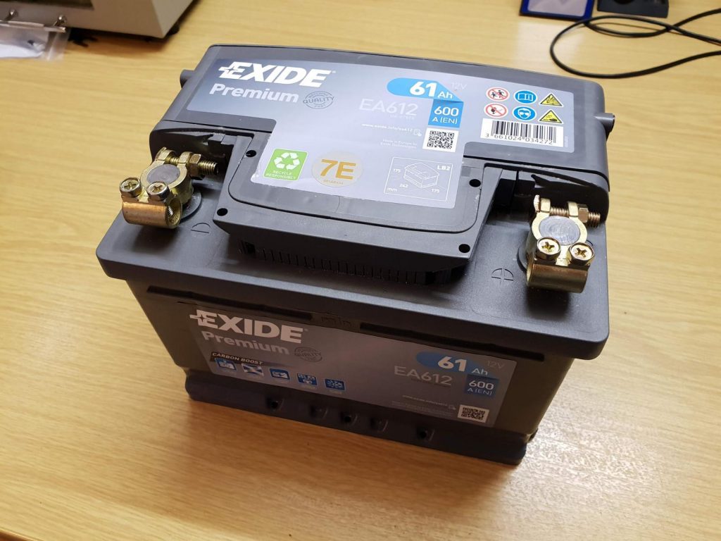
Take your car battery and mount the battery terminals to it.
Important: Please do not connect and use the welder on a car battery that is still installed and connected to your car. Especially not while the car is running. This could cause errors in the car electronics.
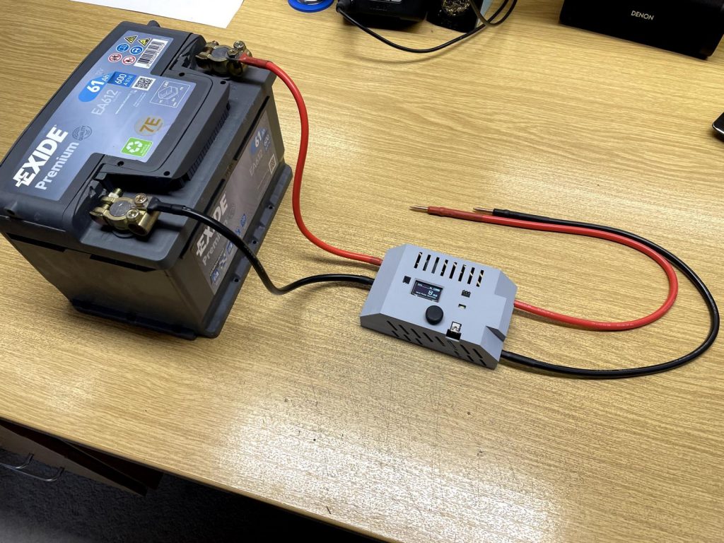
Finally screw the cable shoes of the battery extension cables to the terminals of your car battery. The Spot Welder should start now and is ready to weld. Take good care that the red cable goes to the battery + and the black cable to battery – .Wrong polarity might kill the welder.
Before you start welding please also read the Quick Start Guide.
When you are done with the weld job simply unscrew the welder from the battery. Thats the safest way for storage.
It is also possible to add a switch to the red cable in the 3d printed case that connects from the fuse to the screw terminal. If you do this it is highly recommended to insulate the welding tips with some electrical tape when storing the unit, so they can not accidentally touch something and cause a short circuit.