Arduino Spot Welder Quick Start Guide V3
Please take a minute to read the safety instructions and the quick start guide. If you encounter any problems or have suggestions for improvements feel free to contact us.
General Information
- Input voltage: 10 … 14 V
- recommended welding battery: (you can use car or lipo battery)
- car battery: 12V between 400 and 600 A (CCA)
-
Lipo battery: 3s 5000mAh with minimum 60C (Hobbyking Lipo or SLS Lipo)
- recommended welding material: 0.1mm to 0.25mm nickel strip (most commonly used is 0.15mm)
- Welding cable: 10…16mm², each about max. 50cm long
Quick Start
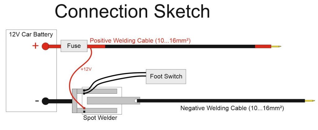
- Connect the welding cables and the spot welder according to the connection sketch. ( Important: Connect the U-shaped aluminum part to the car battery or lipo minus pole, NOT the straight aluminum part )
- (optional) Connect your foot switch to the spot welder (use the white and red wire or white and black on older foot switches)
- (optional) Connect the Fuse/Fuse Case between positive welding cable and battery plus pole
- Set the welding time with the rotary encoder (Display shows weld pulse duration in ms)
- Now you can start welding
For using a 3s Lipo or 12V car battery
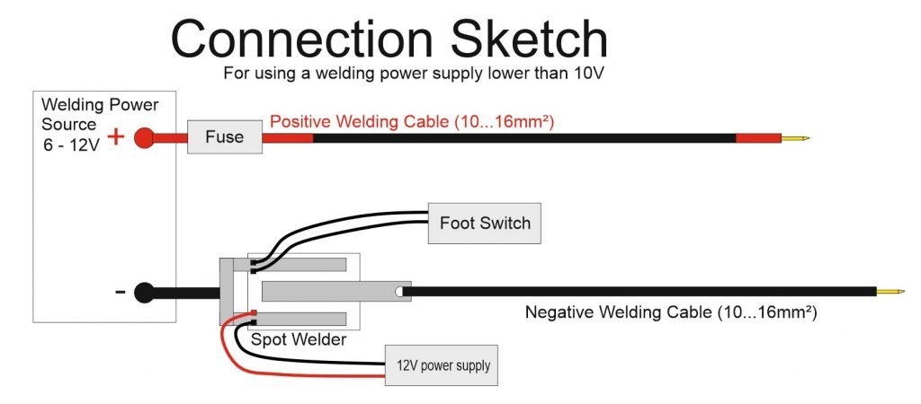
For using a welding power supply lower than 10V (2s Lipo, super capacitors, A123 cells etc.)
Attention: When using this connection method the welder will not be able to measure the voltage of the “welding power source”. So it can not warn you when your 2s lipo is empty. Also it will not be able to show you how much current it is using while welding.
Safety Instructions
Only use this product if you have some basic understanding of electricity. We are dealing with very high currents here which can be dangerous.
The spot welder V3.3 is capable of using up to 800CCA car batteries as a welding current supply. Do not use a car battery that can deliver more Amps. Please note that some car batteries can deliver a bit more Amps as their CCA rating says when used in this application (few ms pulses instead of several thousand ms to start a car). For example a 50Ah 500A (CCA) car battery already works fine to weld 0.1mm to 0.2mm nickel strips to batteries.
Difference between V3 and V3.1…V3.3
Please note that V3 with the one big through hole TVS diode on the mosfet board should only be used with 400 … 600 A (CCA) car battery size to work reliable. Higher CCA car batteries can lead to the destruction of the TVS diode.
V3.1 to V3.3 with the 4 SMD TVS diodes on the Mosfet Board can handle up to 800CCA car batteries.
Additional Safety Tips
If you want to use higher currents or longer welding cables you can do this at your own risk. Absolute maximum rating of the IRFB7430 mosfets is about 1400A welding current.
Do not connect it wrong way around to the car battery. The U-shaped aluminum part goes to the batteries minus (black) pole.
On the first use set the welding time to 3 or 4ms and see how it welds. Then increase the time until you get good welds. If time is set to high, e.g. 20ms for very thin nickel your nickel material will “explode”.
Optional:
For maximum safety do this before the first use:
turn on the Spot Welder, take a multimeter and measure the resistance between the two aluminum parts. It should show arround 150 Ohm (about 1000 Ohm in th elatest version). If it shows 0 Ohm something is shorted out or you got a defective mosfet. (When measurng the voltage between the 2 welding tips you will get your car batteries voltage. That is normal, because the negative welding cable is connected to GND through the 150 / 1000 Ohm resistor)
If you dont have a multimeter you can do this: turn on the Spot Welder, switch off the AutoPulse feature, then put a nickel strip on a piece of wood and put one welding tip on the nickel. Then quickly touch the nickel with the other welding tip. If nothing happens you are good. If you burnt a hole in the nickel strip something is wrong.
The menu and OLED display features (V3.3 Software)
The Main Screen
The main screen has a status bar at the top and the weld time setting as big as possible on the rest of the screen.
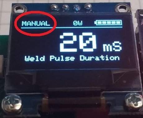
In the Top left corner it will show you if the welder is in “MANUAL” or “AUTO” mode. In manual mode the foot switch can be used to activate a pulse. If it is in auto mode the pulse will be automatically triggered after a short delay when both welding tips touch the nickel strip.
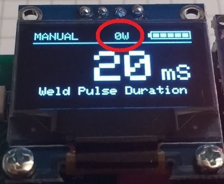
In the middle it will show you the weld counter. This counter increases automatically every time a pulse is activated. It will count up to 9999 and then automatically reset to zero. The “W” stands for welds.
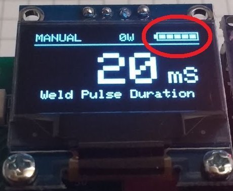
In the top right corner you see the battery bar. On the battery bar the fully charged battery value is set 12.7 V. So for all voltages of your car battery above this value it will display all bars. The lower limit of the battery bar can be set via the “Batt Alarm” item in the main menu. By default it is set to 11 V.
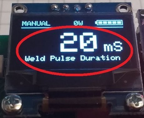
The weld pulse duration can be set by turning the rotary encoder. The maximum is limited to 100ms by default. This maximum can be changed in the sytem menu if necessary.
The Main Menu
You can enter the main menu by clicking the rotary encoder.
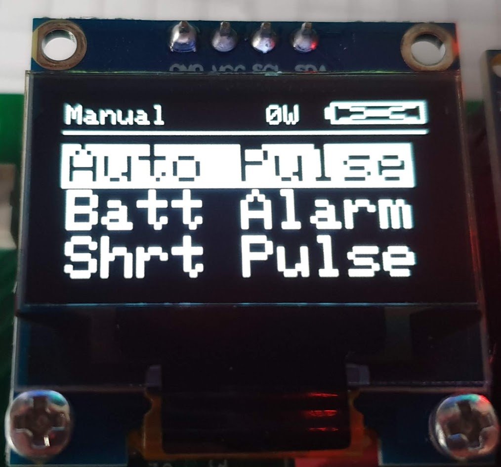
Auto Pulse – opens a sub menu for the Auto pulse settings
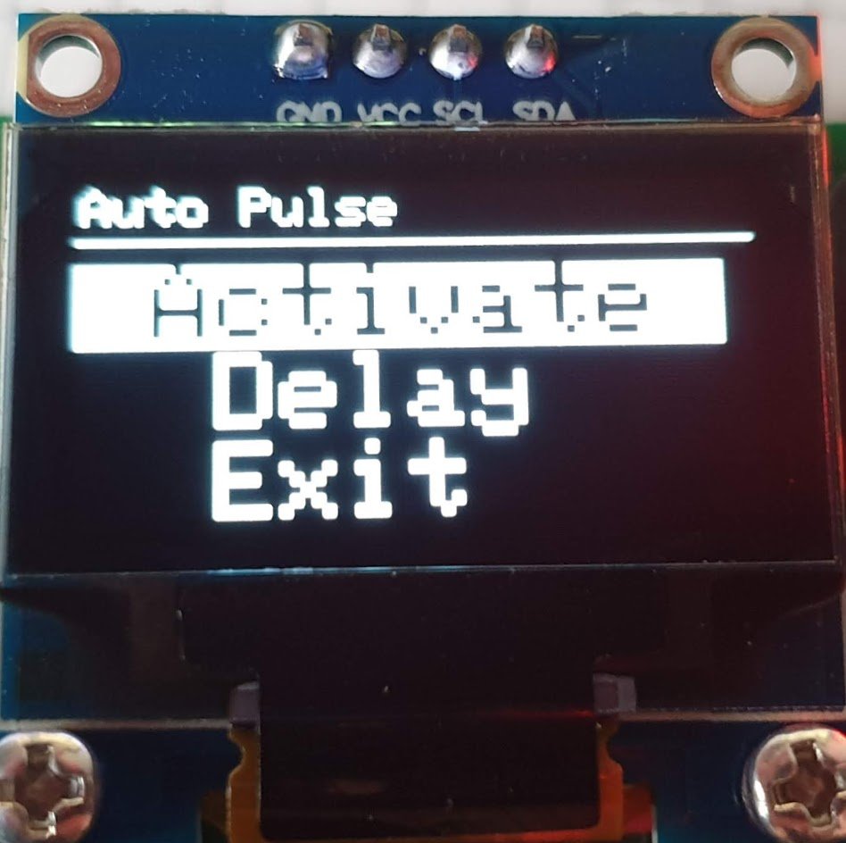
Activate – if you cllick on this you can then switch between “ON” and “OFF” by turning the rotary encoder.
When “ON” is selected the Auto Pulse mode is active. The pulse will be automatically triggered after a short delay when both welding tips touch the nickel strip.
When “OFF” is selected you need to use the foot switch to activate a pulse.
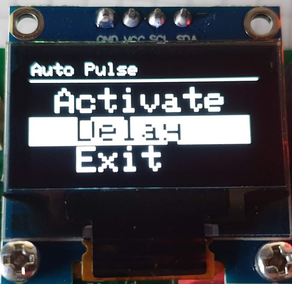
Delay – set the Auto Pulse delay time (delay before a pulse gets triggered when both welding tips touch the nickel strip)
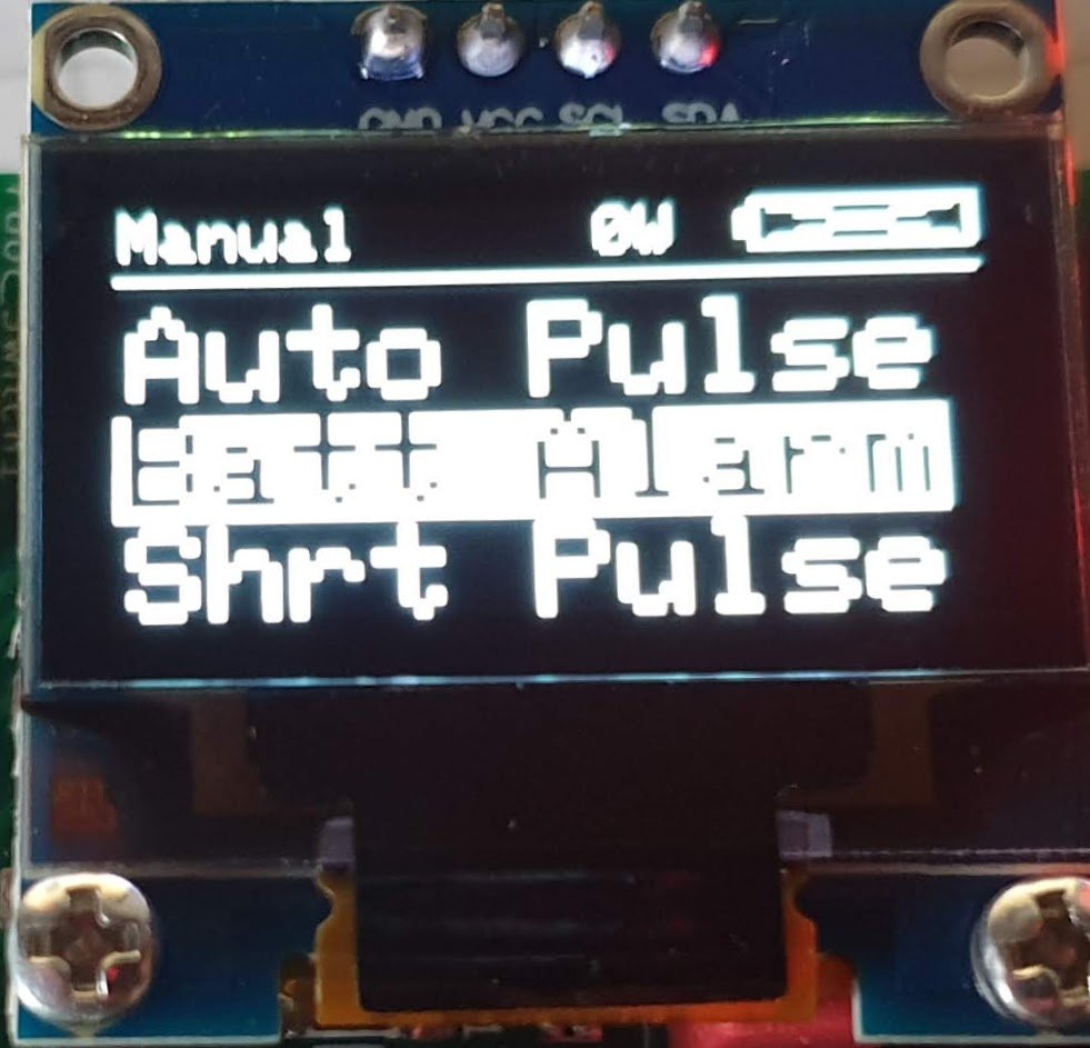
Batt Alarm – set the battery low voltage alarm (default 11.0 V) – this will be the lower limit of the battery bar and the limit to trigger the battery alarm screen
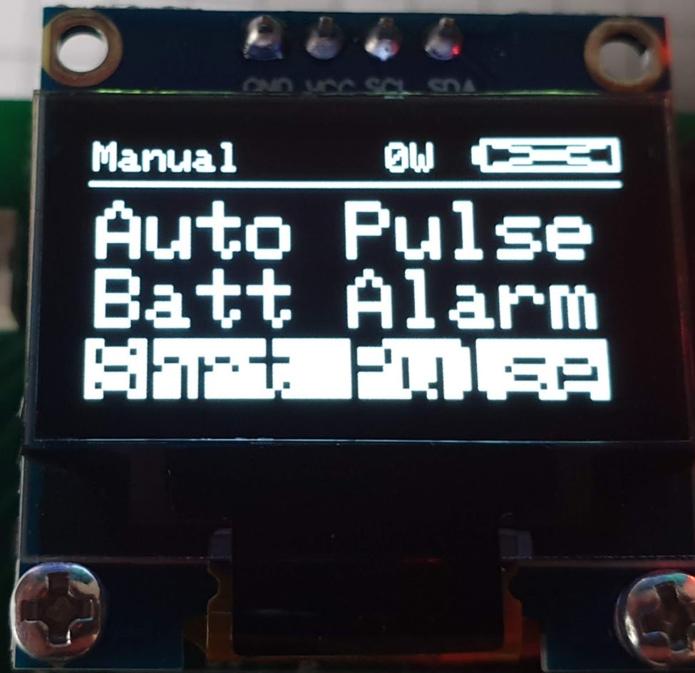
Shrt Pulse – set the short pulse duration (default 12% of the pulse time). The short pulse is meant to preheat and clean the weld Spot before the main pulse happens. You can change it but 12% is usually a good working value.
The percentage can be adjusted down to 0% (0% turns the short pulse off)
On weld times below 3ms the short pulse will be automatically disabled
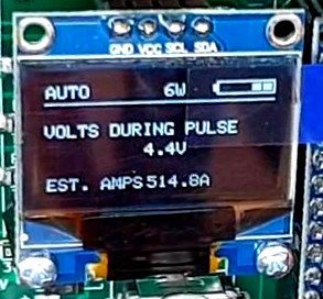
The Weld Pulse Measurement Feature
This feature was introduced with software version 3.2.1 and allows the Spot Welder to measure the voltage drop across the two welding cables and the Spot Welder itself. From that value it then calculates the Amps. The Amp calculation works with a fixed system resistance value of 9mOhm because it is not possible for the Spot Welder to measure the resistance. This means that the Amp calculation will only be accurate if you are using the original welding cables and place the tips on the nickel strip about 1 cm apart.
Also make sure when using the Fuse that you connect the 12V power cable that goes to the Spot Welder to the welding cable side of the fuse. Connecting it to the other side or even directly to the car battery will change the voltage drop the Spot Welder measures and therefore create wrong Amp calculation results.
The measurement will be displayed if you hold down the foot switch for more than 2 seconds after a pulse or if you leave the welding tips on the nickel strip for more than 2 seconds after a pulse. Too leave the measurement screen simply push the rotary encoder button.
The System Menu
This menu is hidden during normal operation of the Spot Welder. You can enter the system menu by holding down the rotary encoder button and then powering up the Spot Welder. As soon as the system menu is displayed you can release the rotary encoder button. There are some new functions in this menu.

Functions in the settings sub-menu:


Max Pulse: sets the maximum welding pulse time that can be set during normal operation on the main screen. The default is set to 100ms. This should be enough for most users, since you can already weld 0.15mm nickel strip on 17ms pulse time with a 440CCA car battery. You can increase this value up to 500ms, however be carefull when using such high pulse times with a powerfull car battery. The mosfets legs may not withstand the high current for such a long time and melt.
Batt Cal: here you can calibrate the measured battery voltage. Due to some parts tolerances the measured battery voltage can be off by 0.1…0.2V. The current measured battery voltage will be displayed. You then measure the actual battery voltage with a voltmeter and enter this value rotating the rotary encoder. Pressing the encoder button causes the offset to be re-computed and saved.

Exit: returns to the system menu
Display: this function can rotate the display by 180°. This is usefull in some mounting configurations of the Spot Welder so you dont have to read everything upside down. Please note that this function only makes sense with a single colour OLED display like on the prebuilt kits. If you are using a two colour display rotating the content 180° will work but it looks messed up.


Functions in the Boot sub-menu:
Reboot: This will reboot the Spot Welder so you dont have to unplug power and power up again to leave the system menu.
Safe Reset: resets all values to factory default except the weld conter, the battery offset and the display orientation and reboots the Spot Welder
Full Reset: resets all values to factory default and reboots the Spot Welder

Info if you build the Spot Welder yourself and using software V3.2.2 or later:
The reboot will only work with Software V3.1 to V3.2.1 and if you do have the “OptiBoot” bootloader flashed to your Arduino Nano. How to do his is shown in the update tutorial. Without the bootloader the Arduino will go to an infinit reboot loop and start blinking. To reboot without the new bootloader simply wait about 5 seconds after you clicked reboot and then unplug power. After this power up the Spot Welder without pressing the rotary encoder to enter the normal operation mode (Main Screen). This also applies to the “Safe Reset” and “Full Reset” menu items.
The menu and OLED display features (Old V3 Software)
The main screen shows the Pulse Time (adjustable by turning the rotary encoder), the battery voltage, the total welds done and if the AutoPulse feature is activated.

You can enter the menu by “clicking” / “pushing on” the rotary encoder.
- Auto Pulse: Here you can turn the AutoPulse on or off and set the delay time. The “AutoPulse” feature automatically activates a pulse after a 2 second delay (default) when both welding tips touch the nickel strip. If it is activated you can not use the foot switch to activate a pulse. The main screen will show “AUTO” in the right bottom corner if it is activated and “MANU” if it is deactivated.
- Btry Alarm: you can set the voltage at which the battery alarm should be triggered (default 11V). If the alarm gets triggered the spot welder will stop working and show a low battery warning until a voltage higher than the set battery alarm is reached. (typically after recharging your battery)
- Shrt Pulse: you can set the duration of the short pulse in % (1 …100) . For example if it is set to 10% and the main pulse is set to 20ms the sort pulse will be 2ms. The short pulse will always be at least 1ms no matter what % value is set. So if the main pulse is 5ms and short pulse is set to 10% it will still be 1ms and not 0.5ms.

If you adjusted something wrong or want the default values back, you can reset the Spot Welder. This will reset all settings except the weld counter.
- hold down the rotary encoder button
- power on the spot welder
- wait 2-3 seconds
- release the rotary encoder button